Wired Methods
Communication Method Support
Our wired communication methods can use Ethernet or fiber optic cables to provide a data connection to the sign site. Ethernet connections may also use an extender device to increase the maximum distance of communication. For software-related issues, please see our Software Support page.
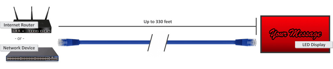
Ethernet
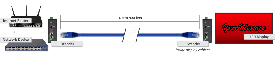
Ethernet with Extender
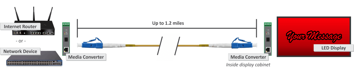
Fiber Optic
Setup
Installing Wired Communication
For freestanding signs, wired communication requires trenching the data cable out to the sign site. All data cables should be trenched in 1.5" conduit. The data connection point for the sign is typically within the leg opposite from the power connection.
For Ethernet cables, it is recommended to use an outdoor grade Cat5e or Cat6 cable such as Belden 7919A or Belden 1594A. A maximum length of 330 feet can be used for Ethernet cables, or 900 feet if purchased with extender devices.
For fiber optic cables, the maximum length depends on the media converter purchased with the sign. Consult your sign specifications for maximum cable length.
Connecting Wired Communication
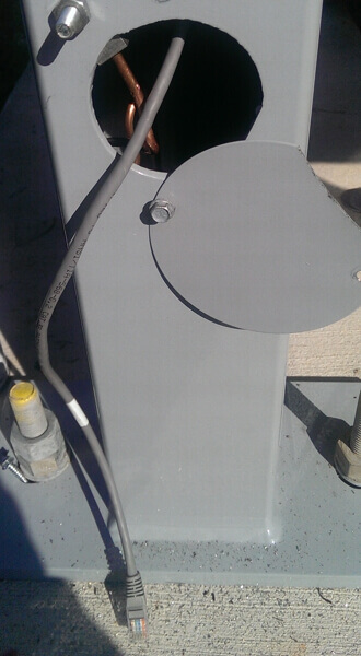
For most freestanding signs, there is an included Ethernet cable that runs from your LED sign's controller to an access panel on one leg. You will be connecting your trenched Ethernet cable to this cable within the access panel, using moisture resistant connectors.
- Open the access panel and locate the Ethernet cables within the leg of the sign. This leg will be opposite the one that contains the electrical lines.
- Pull one cable down from the top of the leg, and the other cable up from the bottom of the leg. Bring both out through the access panel on the sign.
- Cut the connectors from the end of both cables. Always splice, do not use RJ45 connectors to make this connection.
- Make the connections using moisture resistant, gel-filled connectors from manufacturers such as 3M (Scotchlok connectors) or REGAL (JD-UR connectors). These connectors can be purchased at most home improvement centers. Follow the instructions on the packaging.
- It's recommended to keep the individual wire stubs as short as possible and the original wire twist as close to the connector as possible. This reduces electrical interference issues.
- Push the completed connected cable back into the sign leg and replace the access panel cover.